Speedfit Twist & Lock Range
– Specifications
All our technical information for our John Guest Twist & Lock Range of products can be found here.
Speedfit Twist & Lock Range
Style and Description
WaterMarked Fittings
The Twist and Lock range of WaterMarked plumbing fittings were designed for use in normal domestic plumbing applications in accordance with ‘AS/NZS 3500’, ‘AS 4176 (ISO 15875/21003)’. The 12mm range is popular with the caravan and motorhome market.
An additional benefit the Twist and Lock range offers is that a twist of the screw cap locks the pipe into place and gives increased compression on the O-Ring for even greater security.
Media / Application
✓ Potable Liquids
✘ Air / Vacuum
Sizes – Outside Diameter (OD) Pipe
- 12mm (WaterMarked Fittings)
- 10mm, 15mm, 22mm and 28mm (Non-WaterMarked Fittings)
Maximum Working Pressure (kPa)
| Temperature | Pressure | |
|---|---|---|
| POTABLE LIQUIDS | 12mm (WaterMarked) | |
| DO NOT FREEZE | ||
| +1°C | 2000kPa | |
| +20°C | 2000kPa | |
| +70°C* | 1000kPa | |
| Temperature | Pressure | |
|---|---|---|
| POTABLE LIQUIDS | 10mm – 28mm (Non-WaterMarked) | |
| DO NOT FREEZE | ||
| +20°C | 1200kPa | |
| +95°C* | 600kPa | |
*NOT to exceed maximum temperature
Installation Instructions
Step 1
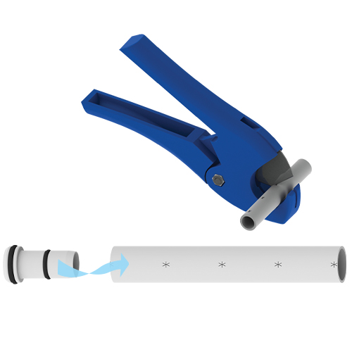
Prepare the Pipe
Ensure the pipe is free of score marks. Cut the pipe square. We recommend the use of JG Pipe Cutters.
To prevent damage to the O-Ring, remove all burrs and sharp edges. When connecting Speedfit pipe, use a Speedfit Pipe Insert. A twisting motion will aid insertion. The insert should only be used with Speedfit pipe.

Step 2
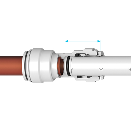
Push Up to Pipe Stop
The fitting should be in the ‘unlocked’ position. This is shown with a small gap between the screwcap and the body flange. Push the pipe fully into the fitting, up to the pipe stop. A good connection has been made.
If you are not using collet clips, ensure that the screwcaps are in the locked position.

Step 3
Twist & Lock
Twist the screwcap until it touches the body flange. This increases the O-Ring seal around the pipe and locks the pipe into position.

Step 4
Pull to Check Secure
Pull on the pipe to check it is secure.
It is good practice to test the system prior to leaving the site, or before use.
Troubleshooting
Pipe Stop Distances
Stops are located at the following distances from the end of the fitting:
| Size | Stop Distances |
|---|---|
| 10mm | 20mm |
| 15mm | 30mm |
| 22mm | 35mm |
| 28mm | 44mm |
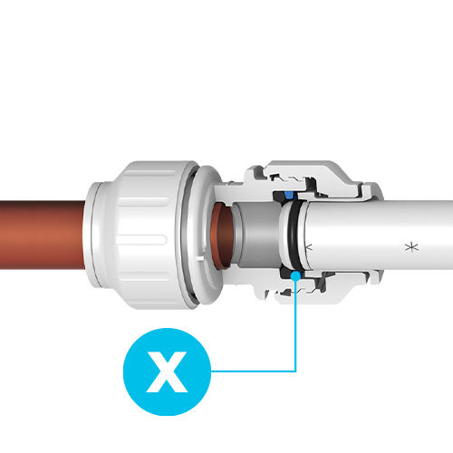
Check Pipe Grip & Depth
Make sure to push the pipe fully into the fitting, past both the collet (gripper) and the O-Ring.
Fitting may be gripped but not sealed if pipe is not fully inserted.
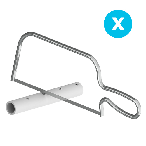
Do not use a hacksaw to cut the pipe.
This will leave unwanted burrs on the end of the pipe.
Do not use damage or scored pipe.
Score marks can cause leaks past the O-Ring.


How to Disconnect

Step 1
Disconnect the Twist & Lock
Ensure that the system is depressurised.
The screwcap on Speedfit Twist and Lock fittings will need to be turned back to the unlocked position.

Step 2
Release the Collet & Pipe
Push the collet square against the face of the fitting by using fingers, or with the help of our collet release tool.
With the collet held in position, the pipe can be removed. The fitting can be used again without the need for replacement parts.
Collet Covers & Clips
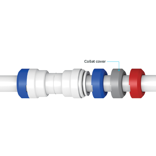
Collet Cover & Clip Applications
Use a collet cover or collet clip to provide added security against pipe disconnection, e.g. the fitting coming into contact with rigid surfaces and behind dry-lining walls.
Collet covers for use with standard Speedfit fittings, are available in white, red or blue to allow colour coding of pipes.
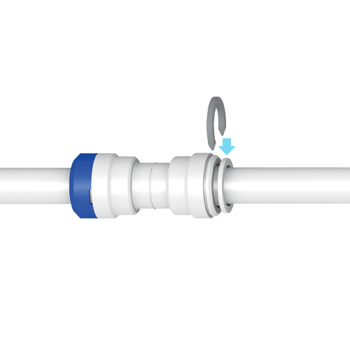
White & Grey Collet Clips
White or grey collet clips are used with standard fittings to prevent accidental pipe disconnection.
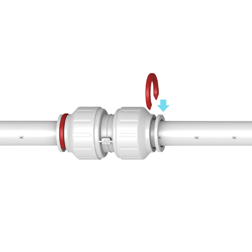
Red & Blue Collet Clips
Red or blue collet clips provide colour coding of pipe on Twist & Lock fittings. They are not designed to prevent accidental release, and should be fitted when the fitting is in the locked position.

Check out the products from family of brands